Daiwa's SV Boost Braking system studied.

Reels are the hottest topic for TackleTour. Everyone wants to know what the latest and greatest is and how they compare to the old guard. What's the best for light stuff, or what's your suggestion for heavy cover. Do we really need different retrieve ratios? It's all in here.
CFDoc
Elite Angler
Elite Angler
Posts: 310
Joined: Wed Jun 19, 2013 12:07 pm

Daiwa's SV Boost Braking system studied.

Post by CFDoc » Tue Aug 23, 2022 8:48 pm

I've had these SV Boost reels a while and I've been really impressed by the braking system. So I wanted to do some more research on them and try to get to the bottom of the technology and really understand what the braking profile looked like during the various parts of the cast.

I know a lot of folks here have mentioned how Lenz's Law, Faraday's induction, EMF, etc. were all governing the characteristics of the SV Boost system. And to be up front, these are all correct statements; however, I wanted to understand a little further and try to get the full relationships for things like braking torque as a function of spool speed, etc. So here's what I've learned...

Basic Principle of Braking System

So I know a lot of you are familiar with how the magnets that surround the inductor attached to the spool help generate an electromagnetic force that acts as a brake to slow down the spool by using Lenz's Law and things of that nature. But after doing a bunch of reading, the specific mechanism that is used in Daiwa's reels is referred to as a Dual Sided Permanent Magnet Radial Flux Eddy Current Braking System. It's a heck of a word salad to digest but each word is important, and you will often see the DSPM abbreviation when describing these systems.

Dual Sided - Refers to the fact that there is an inner layer and outer layer of magnets that surround the inside and outside of the inductor rotor, respectively.

Permanent Magnet - Refers to the fact that the magnets that surround the inductor rotor are not electromagnetically driven, they are permanent.

Radial Flux - Refers to the fact that the magnetic forces are acting radially, not axially, against the inductor rotor. This matters because there are DSPM braking systems based on Axial Fluxes as well as Radial Fluxes.

Eddy Current - Refers to the fact that the braking system generates Electromagnetic Eddy Currents in the inductive rotor to ultimately brake the rotor.

After doing a bunch of reading of the literature, I found three articles that do a very good job of explaining, in detail, how these systems work. I'll be referencing these three articles a good bit here:

(1) https://ietresearch.onlinelibrary.wiley ... .2013.0050

(2) https://ieeexplore.ieee.org/document/1381503

(3) https://link.springer.com/article/10.10 ... 017-0636-x

The starting point for describing a DSPM braking system is to consider the case where the spool has a constant angular velocity, the dial is set to maximum braking (setting 20 for my Zillion SV TW), and the inductor is fixed in a given position (i.e. - not moving in or out relative to the magnets). A general diagram of this is provided below and was taken from Reference (1).

Image

This picture shows the basic outline of the inner and outer ring of magnets with a total of 12 magnetic poles (6 poles on the inner/outer ring, three 'N' and three 'S' poles per ring, total of 12 poles), and an inductor surface sitting in between the inner/outer rings.

I was able to verify that Daiwa used this setup for their braking system by removing the outer ring from my Zillion SV TW and running a small nail around the edge and counting the number of times the nail attracted/repelled from the ring. I put a picture of the ring below:

Image

After doing this, I counted 6 total poles on the outer ring. Three 'N' and three "S" poles. I then verified that the inner ring had another 6 poles in a similar pattern so the setup matched the diagram in my first figure.

Once I was convinced that Daiwa was using the DSPM Radial Flux mechanism for their braking, I started studying the braking torque relationships as a function of spool speed for a fixed inductor setting. So to be clear, this would be the relationship between braking torque on the spool at a given spool speed assuming that the inductor does not move in or out. Reference (1) and (2) provides analytical relationships for Torque vs. spool speed with Reference (1) including a lot of important effects such as 3D shapes, reactions fields induced by the rotor, etc. That function is provided in the figure below:

Image

When I first saw this formula, I really couldn't believe how complex it was and I was further shocked that Daiwa would need such a complex function to slow down a spool during a cast. For comparison, other braking systems usually have some simple linear, quadratic, or simple variation on those two functions to yield their braking torque vs. spool speed relationships. For a quick example on how crazy that function is, everywhere you see the parameter 'm' in that equation, that's another crazy function of spool speed that is defined in the Appendix of Reference (1). So spool speed is an insane combination of trigonometric, exponential, and hyperbolic functions as it relates to torque.

All three of the references provide a lot of figures that show what this function looks like for a lot of different combinations of magnets, inductors, speeds, geometry, etc. Here's one example below:

Image

Looking at this figure (and a bunch of others), I started noticing that all of the curves can be broken into three separate sections. The first part, at the lower RPMs, is basically linear. As the RPMs get higher, there is a tapering off to a maximum. As the RPMs continue to increase beyond the maximum braking torque, the torque falls off and continues to fall until there is a point where RPMs are crazy high and braking torque is essentially nothing.

Reading further in Reference (1), I saw where they stated that the 'operational regime' of most DSPM's is in that linear range there at the lower RPMs. I even cropped a diagram from that paper that shows how they put a grey box around where they would expect the DSPM brake to actually be working. That picture is below:

Image

Seeing this, it makes me wonder if Daiwa does something similar? I wonder if they designed their DSPM such that the torque relationship with spool speed remains in that linear range for a given inductor position and spool speed. If anybody knows for sure, I'd love to hear it.

Regardless, Daiwa gives us two ways to adjust the magnetic/electromagnetic field to change the overall braking profile. The first way is by giving us the dial on the outside of the reel that can go from 0 - 20 in settings. The next way is they allow the inductor to move in/out of the concentric permanent magnets as the spool speed increases/decreases, respectively.

I'll discuss the effect the dial has on the magnetic field first, and then the inductor moving in/out next.

Adjusting the Magnetic Field/Braking Dynamics With the Dial

For the longest time, I was convinced that turning outside dial on these SV Boost reels moved the magnets closer to/further from the spool. Boy was I wrong. What actually happens is that when you turn the dial, the outer ring of magnets rotates about the center of the spool shaft. If you go back to my second picture, you can see the gear toothed track that the outside ring has that connects to the dial.

Looking closer at the two magnet rings, I saw that there are two 'notches' in the plastic part of the rings. When the dial is at maximum (setting 20), these two notches line up. This is shown in the picture below. You can see the notches just above the two blue lines.

Image

Next, I put the dial on minimum (setting 0) and marked the location of the notches again. You can see that the outside notch has rotated by looking at the figure below:

Image

So what's happening here? If you go back to the very first picture I posted that shows a typical DSPM setup, it represents exactly what Daiwa has when the dial is set to the maximum braking setting. So all N magnetic poles on the inner ring line up exactly with an S pole on the outer ring.

When the dial is turned, this is not the case. The N poles from the inner ring will start to overlap with N-S poles from the outer ring. And when you get to the minimum brake setting, what you end up with is N poles from the inner ring lining up exactly with an N pole on the outer ring.

When the dial is set such that the N and S poles don't line up with each other (basically any other setting than 20), the magnetic flux gets reduced. This reduction in magnetic flux causes a reduction in electromagnetic flux generated by the inductor. This then reduces the amount of torque that the inductor can impart on the spool.

Now what I haven't been able to figure out yet is what effect the different dial settings has on the torque vs spool speed relationship. Is the formula I presented in the picture above still valid? Is there still a linear relationship, followed by a maximum, followed by a falloff of torque? If anybody knows the answer to this, I'd love to know.

One thing I am fairly certain of is that when the dial is at zero, and the N pole from the inner ring aligns with the N pole from the outer ring, the two current densities from the inner and outer magnets will cancel each other out and there would be no torque on the spool at any speed.

It's the blended N-S pole overlaps that I'm less sure about.

Adjusting the Magnetic Field/Braking Dynamics With the Inductor Rotor

The final way in which Daiwa manipulates the magnetic field to control the braking profile is that the inductor is attached to springs which will push the inductor in/out of the magnetic field at high/low spool speeds, respectively.

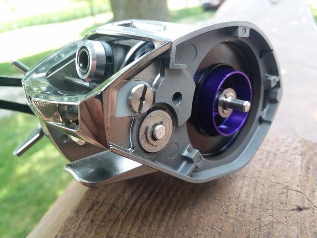
Below is a picture of how the inductor is installed on the spool shaft with the two springs that help control inductor position at various spool speeds.

Image

You will notice the 'ramp' on the bottom of the inductor. That ramp fits flush with another ramp attached to the base of the spool. So when a torque is applied to the inductor rotor, the rotor will travel up the ramp until the springs are strong enough to either hold the inductor in place, or push the inductor back down to the base of the spool.

For the longest time, I was convinced that centrifugal force is what pushed the inductor into the magnets. Nope! It is the torque that is applied from the electromagnetic field that twists the inductor relative to the spool. That twisting is what then pushes the inductor into the magnetic field.

To prove this, I attached the spool to my Dremel drill and turned it up. The inductor did not move regardless of the speed of my Dremel. I took a video of this and if anybody has a YouTube account, I will email you the video to post. However, I did take a snapshot from the video and posted it below.

Image

Hopefully, this photo helps show that the spool is spinning but the inductor is not extended at all.

Ok, to wrap this up. I was trying to figure out what Daiwa was trying to achieve by tying the position of the inductor to the torque generated by the electromagnetic field. And the best I can do at this point is the following thought experiment...

Put the dial back at maximum braking so the N-S and S-N poles are aligned. Now assume that the braking torque is a linear function of spool speed (from previous arguments). Now go back and look at that complex formula and notice that inductor length, L, is linearly related to torque. So by saying torque is a linear function of spool speed, and then further stating that inductor length is linearly related to torque, you can then say that torque would be a quadratic function of spool speed.

I plan on doing some more work on this. Namely, coding up the math to see what torque/speed curves look like for an actual Daiwa SV Boost spool. But if anybody has any more input, I'd love to hear it.

Hope this helps.
Last edited by CFDoc on Wed Sep 07, 2022 8:19 pm, edited 2 times in total.

User avatar
LowRange
Pro Angler
Pro Angler
Posts: 4804
Joined: Wed Jun 15, 2016 9:18 am

Re: Daiwa's SV Boost Braking system studied.

Post by LowRange » Wed Aug 24, 2022 6:51 am

Here are some cool videos to add to the discussion.

This one shows animations of the magnetic field and mag dial operation as well as Magforce Z/3D operation.
https://youtu.be/_KqMoncLkH0

This one's shows the effects of the magnetic field on a square of film.
https://youtu.be/luQMCR7_nvY

Also I'll add that the reel, or rather the magnets, also greatly impact braking profile. For example if you wanted a more free casting SV Boost you can drop the Zillion 1000 spool into a Steez TW SV. Something about that combination of spool and reel wakes up the spool more. Going further you can place it in the 1st gen Steez later interarion reels like the gen 1 Steez LTD and get even further reduced braking but you have to run the dial very high because you are on the bleeding edge. Those old Steez have very weak magnets in comparison to modern reels.

Another componet is the distance of the magnets rather than their strength. Some reels like the TD-Z and other old Daiwa platforms have magnets very far away from the spool. This means that when the inductor is seated against the spool near the end of the cast there is less aluminum in the magnets and even more reduced braking producing a more free braking profile. In reels with Magforce 3D like we see in the 1st video you can even adjust the distance between the magnets and spool essentially allowing you to adjust braking profile with the 3D selector and braking strength with the magnet dial. It's really great system that Daiwa has unfortunately abandoned.
Last edited by LowRange on Wed Aug 24, 2022 8:29 am, edited 3 times in total.

User avatar
LowRange
Pro Angler
Pro Angler
Posts: 4804
Joined: Wed Jun 15, 2016 9:18 am

Re: Daiwa's SV Boost Braking system studied.

Post by LowRange » Wed Aug 24, 2022 7:23 am

To the question of "is the magnets and inductor braking effect a linear interaction"

Yes and also no. It depends on the spool. As the spool spins and the magnets field strength and proximity to the spool remains the same then the braking force applied to the spool has a linear relationship to spool speed. Speed goes up then braking goes up. If there is portion of the spool that can move to and from the magnets (such as the inductor) using centrifugal forces and spring or twisting ramps and a spring (or two) then that relationship becomes non linear. It becomes non linear because the inductor has varying amounts of inductor in the magnetic field, typically a lot in the beginning of the cast and decreasing amounts near the end compared to a fixed inductor.

With fixed inductor spool the braking profile is basically linear. It certainly acts that way be it a Daiwa or a Black Max. On a hard distance cast with a magnetic setting to prevent overrun early in the cast a linear magnetic brake will often feel overbraked or "choked off" at the end of the cast. Backing off of the magnets to free up the end of the cast will often result in insufficient braking in the beginning of the cast producing a backlash. Linear magnetic brakes do not respond well to a whippy/snappy cast. You need a non linear braking profile to absorb that initial shock and then free up after later in the cast. With linear magnetic braking its better to use a lower dial setting that allows for a free cast at the end and, this is key, a smoother casting stoke to prevent overruns early in the cast. You can't whip the rod with linear magnetic spools. They do not like it and all you are going to do is chase your own tail going up and down on the dial.

Each has their time and place. Linear magnetic especially when paired to light weight spools and proper casting technique makes for effortless and consistent casting of baits. This really pairs well with target casting lighter or awkward baits and casting into wind. The non linear and especially the distance tuned non linears with heavier spools do well with hard bomb casts at a high release points with baits that cast well.
Last edited by LowRange on Wed Aug 24, 2022 8:33 am, edited 1 time in total.

User avatar
LowRange
Pro Angler
Pro Angler
Posts: 4804
Joined: Wed Jun 15, 2016 9:18 am

Re: Daiwa's SV Boost Braking system studied.

Post by LowRange » Wed Aug 24, 2022 8:17 am

Even more food for thought on braking profile.

What about the inductor and spring?

Spring rate also plays a large role in braking profile. We have stiff springs like the HLC spring found on HLC spools that retract the inductor much sooner than other softer spring spools and dual rate or dual spring spools that have both a soft and stiff spring.

We also have variations is inductors like length, thickness and tapered/non tapered to consider. Based on my operations, long inductors seem to offer a smoother braking profile with softer transitions between the inductor being extended and seated. Thin/thick inductors seem to mostly effect braking strength with a short thick inductor having more of an on/off braking profile and a long thin inductor a more smooth transition. An example of this is my IP spools. They have stiff springs and short thick inductors. They brake pretty hard when extended and kind of go to "off" and are very free which can make for some line fluff with heavier non braids over 14#. On the other hand my Z200 has a long thin inductor with stiff spring. On all around its a smooth casting reel and even handles long cast mode well without being too on/off in braking profile.

The tapered inductors are where things get wild. They have a beveled leading edge and the purpose is to reduce the amount of inductor in the magnets when the inductor is seated. This was done to make for a free casting spool at lower spool speeds. Examples of this are the Type R, Type R+, Pixy Airy Red, Zonda and TD Zillion HLC spools. The Type R+ being a favorite of mine in that it has a softer spring to make it less wild but still retains the tapered inductor. One of these in a TD-Z will still go toe to toe with a Zillion 1000. Things get wild when you pair that tapered inductor to an HLC spring. This is what the TD Zillion HLC did and its a monster of a spool. Its beaten many men that dared to put non braid on it, cast too softly or used the wrong kind of baits. It's no joke.

I went a step further and took my tapered Zonda spool and added an HLC spring. The goal was to make an Alphas HLC. It worked but had an extreme on/off braking profile that I had to subdue with spool tension and reduced mag brake. With no tension and make brake only it would cast fine then go free spool way too early and blow up. It was like getting a blow up because you had the brakes too low but way later in the cast out of nowhere. It was that inductor snapping back down way too soon. I really need to drop the spring down to a slightly softer spring on that one. This is just part of tinkering. Speaking of tinkering you can also very easily swap SV spool inductors with inductors from other SV spools or aftermarket inductors to alter braking profile. Unlike Magforce Z/V where there are lots of different brake types with little compatibility, pretty much all non Boost SV spools can swap inductors. Daiwa's own run the range from long/short and thin/thick. Reels like the SS SV and 17 Tatula SV have long and thick inductors where as the Alphas SV105 has a shorter and thinner inductor. Inductors from the Ray's Studio spools come in a gold long and thin as well as a short thicker but tapered inductor. I'm a fan of Ray's swapping the thin gold ones on SV spools to wake them up. It comes at the cost of easy skipping but really solves the "choked off" problem.

Zonda spool tapered inductor

Image

CFDoc
Elite Angler
Elite Angler
Posts: 310
Joined: Wed Jun 19, 2013 12:07 pm

Re: Daiwa's SV Boost Braking system studied.

Post by CFDoc » Wed Aug 24, 2022 8:43 am

Thanks for the discussion, LowRange. Those videos are nice and I ordered some magnetic viewing film to put on my Zillion and Alphas SV TW’s. Hopefully I can get some measurements off the SV Boost system and plug them into that formula and start plotting the actual braking profile vs spool speeds.

Regarding the springs, I am still working to derive the Free Body Diagram of forces on the inductor that would cause the axial motion. You’re correct, the springs make a huge difference.

From what I’ve seen so far, even though the two springs are in series, they don’t really act like it. This is because the spring rates between the two springs are so different, it actually acts more like two separate systems.

So for example, a true two series springs model will act like one spring with an effective spring constant that looks like:

1/ke = 1/k1 + 1/k2

But with the SVBoost springs, k2 >> k1. So what happens is, initially the inductor moves like it’s only attached to the weak spring. Then the weak spring gets fully compressed and it’s spring rate goes to infinity. Then the Inductor is allowed to move along as if there’s only the strong spring.

User avatar
LowRange
Pro Angler
Pro Angler
Posts: 4804
Joined: Wed Jun 15, 2016 9:18 am

Re: Daiwa's SV Boost Braking system studied.

Post by LowRange » Wed Aug 24, 2022 8:59 am

Another consideration in spool selection in braking profile is the baits you intend to throw. This gets overlooked but it is a big part of the equation and the results can be disastrous.

The recent Steez HLC has demonstrated this. That reel as an HLC has a very fast spool. It wants to bomb baits but you need to use baits and line that is conductive to bombing. You can't go buy the bomber reel and expect that it will make any bait bomb. It will often have the opposite effect and cast some baits worse than a reel with an appropriate braking profile for the bait. Pairing heavy flouro to an HLC and throwing Texas rigs is a recipe for disaster yet this is what people did. Daiwa really didn't do a good job of informing people on what an HLC really is.

I have two spools I use in my LIN10. One is a wild 1016 that casts like an HLC because something is off about it. The other is the stock spool. Pictured below is the wild 1016 dumping all 50# braid without even trying throwing a frog and other is the sock spool that I had to cast very very hard to gen get it to cast even that much line off the spool and get it still has quite a few spool revolutions of line. There was no contest between the two with the same frog. Clearly the wild 1016 was the better distance caster of the two.

What was interesting is that when casting baits that don't bomb well and struggle a bit casting I found that I had the run the brakes so high on the fast spool that I was getting less distance than the spools that clearly demonstrated earlier that is was a slower spool. With that slower spool I could run the dial lower and really lay into it on the cast and cast the same non bomb friendly baits with greater distance. That was a nice surprise.

The point is you can't take a fast spool and give it a bait it doesn't like to cast and expect it to behave let only force the bait into becoming a long casting bait. I see this with my Z200. On long cast with a shallow Big M I can bomb that thing nearly down to the arbor of 65# braid. Same settings throwing a glide bait doest get me any more distance than a fixed inductor and actually gets a ton of fluff and runs the risk of a break off. The glides I throw simply don't cast anything like the weight transfer Big M so all that spool speed doesn't do me any good.
Attachments
Screenshot_20220824-105603_Chrome_copy_651x1139.jpg
Screenshot_20220824-105603_Chrome_copy_651x1139.jpg (58.46 KiB) Viewed 3392 times
Screenshot_20200719-223434_Gallery_copy_720x947.jpg
Screenshot_20200719-223434_Gallery_copy_720x947.jpg (65.28 KiB) Viewed 3392 times

CFDoc
Elite Angler
Elite Angler
Posts: 310
Joined: Wed Jun 19, 2013 12:07 pm

Re: Daiwa's SV Boost Braking system studied.

Post by CFDoc » Mon Aug 29, 2022 3:30 pm

So I bought some magnetic viewing paper. For reference, this is what I bought and how it works: https://m.youtube.com/watch?v=slVL5nbTXd4

I’ll post pictures of the magnetic fields at various dial settings from my Daiwa Zillion SV TW as well as the magnetic rings when separated from each other and viewed individually.

So this first picture is what the magnetic field looks like when the inner and outer magnet rings are viewed individually.

Image

From that reference video. It says that white lines are when the magnetic field is facing parallel to the paper (away from a pole) while dark areas are when the field is perpendicular to the paper (on a pole). However the paper cannot distinguish a N from a S pole.

So this picture still confuses me as the ring only shows one white line, not two. I would have thought there would be two white rings following the edge of the circle. Someone smarter than me is welcome to explain it to me.

The white lines traveling outwards from the center make sense because this is where the field goes from a N pole to a neighboring S pole so there’s a parallel running of the field.

This next picture has the magnets back in the reel as they are when the side plate is out back on and the dial is at maximum brake (setting 20).

Image

For this setting, an N pole on the inner ring lines up with an S pole on the outer ring. So this is why you see white lines in between the two rings as the magnetic field needs to turn parallel to the paper twice, one for each pole. They even have to make a squiggly trail between each other so an N pole can meet an N pole that is offset.

Next, the picture below shows the dial setting at minimum braking (setting 0). Now the white lines are very clean and circular as an N pole on the outer ring sits directly above a N pole on the inner ring

Image

Finally, the last picture below shows the dial at the middle setting (setting 10). You can see the convoluted magnetic field where the N poles from the top are trying to find there way to the N poles below and make a sort of jagged path to get there.

Image

Hope y’all find this interesting. Still trying to figure out how these various setting change the overall torque/speed relationships during casting.
Last edited by CFDoc on Wed Sep 07, 2022 8:30 pm, edited 1 time in total.

User avatar
doomtrprz71
Elite Angler
Elite Angler
Posts: 408
Joined: Tue Jan 14, 2014 4:35 am

Re: Daiwa's SV Boost Braking system studied.

Post by doomtrprz71 » Mon Aug 29, 2022 5:54 pm

CFDoc wrote:
Mon Aug 29, 2022 3:30 pm
So I bought some magnetic viewing paper. For reference, this is what I bought and how it works: https://m.youtube.com/watch?v=slVL5nbTXd4

I’ll post pictures of the magnetic fields at various dial settings from my Daiwa Zillion SV TW as well as the magnetic rings when separated from each other and viewed individually.

So this first picture is what the magnetic field looks like when the inner and outer magnet rings are viewed individually.

Image

From that reference video. It says that white lines are when the magnetic field is facing parallel to the paper (away from a pole) while dark areas are when the field is perpendicular to the paper (on a pole). However the paper cannot distinguish a N from a S pole.

So this picture still confuses me as the ring only shows one white line, not two. I would have thought there would be two white rings following the edge of the circle. Someone smarter than me is welcome to explain it to me.

The white lines traveling outwards from the center make sense because this is where the field goes from a N pole to a neighboring S pole so there’s a parallel running of the field.

This next picture has the magnets back in the reel as they are when the side plate is out back on and the dial is at maximum brake (setting 20).

Image

For this setting, an N pole on the inner ring lines up with an N pole on the out ring. So this is why you see white lines in between the two rings as the magnetic fields are ‘pushing’ against each other. They even have to make a squiggly trail between each other so an N pole can meet an S pole that is offset.

Next, the picture below shows the dial setting at minimum braking (setting 0). Now the white lines are very clean and circular as an N pole on the outer ring sits directly above a S pole on the inner ring

Image

Finally, the last picture below shows the dial at the middle setting (setting 10). You can see the convoluted magnetic field where the N poles from the top are trying to find there way to the S poles below and make a sort of jagged path to get there.

Image

Hope y’all find this interesting. Still trying to figure out how these various setting change the overall torque/speed relationships during casting.
That's awesome, the convoluted field is interesting for sure.

Dalleinf
Platinum Angler
Platinum Angler
Posts: 1460
Joined: Wed Dec 10, 2014 1:12 pm
Location: Denmark

Re: Daiwa's SV Boost Braking system studied.

Post by Dalleinf » Mon Aug 29, 2022 9:30 pm

Very interesting - thank you for the write-up.

User avatar
y2k88
Platinum Angler
Platinum Angler
Posts: 1168
Joined: Sun Mar 27, 2005 11:41 pm
Location: Australia

Re: Daiwa's SV Boost Braking system studied.

Post by y2k88 » Tue Aug 30, 2022 4:43 am

Very imteresting.

Wondering if it would be more applicable if the sheet was placed between the inner and outer magnets, rather than on top of both. As I assume you’d be most interested in the magnetic field lines directly between the two cylinder magnets, rather than the side of the cylinder. :-k

CFDoc
Elite Angler
Elite Angler
Posts: 310
Joined: Wed Jun 19, 2013 12:07 pm

Re: Daiwa's SV Boost Braking system studied.

Post by CFDoc » Tue Aug 30, 2022 6:47 am

y2k88 wrote:
Tue Aug 30, 2022 4:43 am
Very imteresting.

Wondering if it would be more applicable if the sheet was placed between the inner and outer magnets, rather than on top of both. As I assume you’d be most interested in the magnetic field lines directly between the two cylinder magnets, rather than the side of the cylinder. :-k
Working on that at the moment. You have to be careful with this paper. Apparently creasing/tearing etc. makes it not work properly.

So finding a way to get the paper into the gaps and be able to see it is turning out to be quite difficult.

My thought was that the magnetic field was somewhat consistent at you progressed from the edge of the rings into the center of the rings axially. Some of those papers tend to draw that conclusion since they integrate along the entire length of the inductor.

Regardless, it’s a very valid thought and I’m working to get the paper inside those rings…

User avatar
jvelth74
Platinum Angler
Platinum Angler
Posts: 944
Joined: Fri Aug 24, 2018 7:03 am
Location: Finland
Contact:

Re: Daiwa's SV Boost Braking system studied.

Post by jvelth74 » Tue Sep 13, 2022 4:25 am

Does that part '114' (plastic part connecting stiff spring to weak spring) anything more than just connects springs together and supports springs?
https://www.plat.co.jp/parts/DAIWA/STEE ... 630201.pdf
Or has it any effect to spring compression or inductor movement?

...And furthermore, is sv Boost nothing more than two (very) different springs connected together in a series?
https://www.youtube.com/watch?v=Py7qnXtMIUA

Some person wrote that part '114' hits to inductor. If that is true, it's obviously made before than soft spring is fully compressed. (Maybe for protect soft spring not to be damaged?)

And if so, then spring rate before part '114' connects to the inductor, spring rate is:
1/ke = 1/k1 + 1/k2
Or is it?

And after part '114' connects to inductor, spring rate is:
1/ke = 1/k1 => ke = K1, (if stronger spring is K1)
Or is it?
Last edited by jvelth74 on Tue Sep 13, 2022 5:32 am, edited 1 time in total.

User avatar
LowRange
Pro Angler
Pro Angler
Posts: 4804
Joined: Wed Jun 15, 2016 9:18 am

Re: Daiwa's SV Boost Braking system studied.

Post by LowRange » Tue Sep 13, 2022 5:29 am

jvelth74 wrote:
Tue Sep 13, 2022 4:25 am
Does that part '114' (plastic part connecting stiff spring to weak spring) anything more than just connects springs together and supports springs?
https://www.plat.co.jp/parts/DAIWA/STEE ... 630201.pdf
Or has it any effect to spring compression or inductor movement?

...And furthermore, is sv Boost nothing more than two (very) different springs connected together in a series?
https://www.youtube.com/watch?v=Py7qnXtMIUA

Some person wrote that part '114' hits to inductor. If that is true, it's obviously made before than soft spring is fully compressed. (Maybe for protect soft spring not to be damaged.)

And if so, then spring rate before part '114' connects to the inductor, spring rate is:
1/ke = 1/k1 + 1/k2

And after part '114' connects to inductor, spring rate is:
1/ke = 1/k1, (if stronger spring is K1)
I don't belive so. It acts as a holder or cartridge for the two springs. It is possible that the thickness of the flange can affect braking profile by limiting how much of the inductor extends into the magents similar to how an extra shim can be used on top of the spring in Magforce Z reels. Aliexpress sells this part in various colors.
US $15.00 | DIY SV boost spool part Suitable for 21 ZILLION 100H STEEZ LTD
https://a.aliexpress.com/_mPlUlbe

User avatar
jvelth74
Platinum Angler
Platinum Angler
Posts: 944
Joined: Fri Aug 24, 2018 7:03 am
Location: Finland
Contact:

Re: Daiwa's SV Boost Braking system studied.

Post by jvelth74 » Tue Sep 13, 2022 5:47 am

Lowrange, that is possible. Actually I don't know. I don't have sv Boost spool, so I can't check it.

But I think it is possible that firstly inductor presses both springs, when spring rate is 1/ke = 1/k1 + 1/k2, and after some compression part '114' touches to inductor and after that soft spring doesn't compress anymore, and the spring rate is ke = K1, because now it's compressing only stiffer spring.

Anybody who has sv Boost spool, could you check how it works?

User avatar
LowRange
Pro Angler
Pro Angler
Posts: 4804
Joined: Wed Jun 15, 2016 9:18 am

Re: Daiwa's SV Boost Braking system studied.

Post by LowRange » Wed Sep 14, 2022 7:41 am

jvelth74 wrote:
Tue Sep 13, 2022 5:47 am
Lowrange, that is possible. Actually I don't know. I don't have sv Boost spool, so I can't check it.

But I think it is possible that firstly inductor presses both springs, when spring rate is 1/ke = 1/k1 + 1/k2, and after some compression part '114' touches to inductor and after that soft spring doesn't compress anymore, and the spring rate is ke = K1, because now it's compressing only stiffer spring.

Anybody who has sv Boost spool, could you check how it works?
That sounds correct as far as full extension is concerned. I think a thicker spacer between the two springs (part 114) would not allow the inductor to extend as deeply into the magnets. This would make the spool brake less at high speed but may not affect low speed braking much if at all. No way to know if it is an improvement or not until you try.
I've made more than one spool unusable by tinkering. :lol:

Post Reply